Back to work

L5 · 3D teardown

Integrated robot joint

Separate fourteen parts around a hollow axis. Follow power, torque and dual-encoder feedback.

Drag to rotate · Scroll to zoom · Click a part for detailsDrag to rotate · Pinch to zoom · Tap a part for details
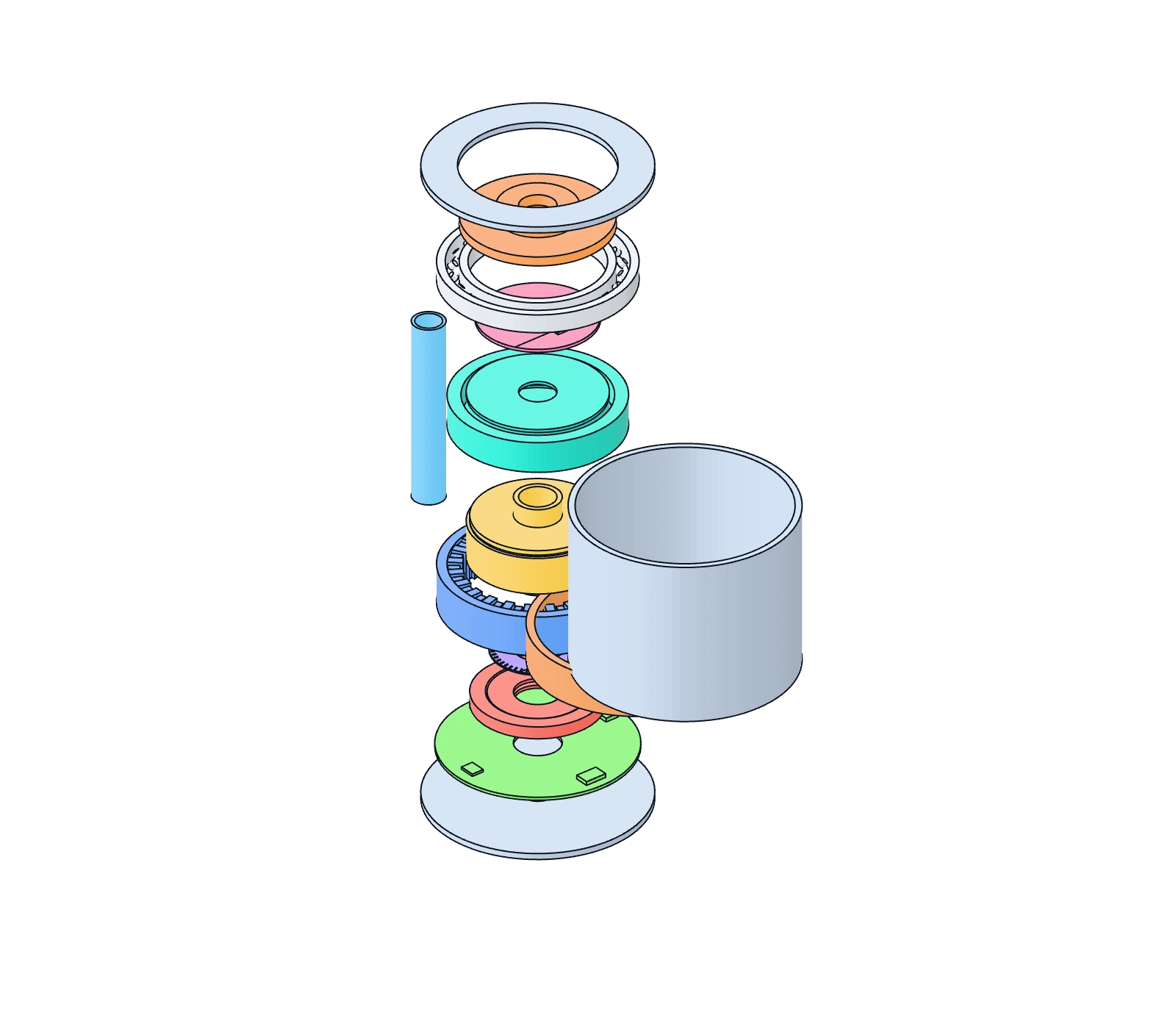
Original hollow robot joint exploded schematic showing a motor, harmonic reducer, dual encoders, brake, driver board, bearing, housing and covers.

Selected part Motor stator

Winding currents establish the magnetic field that interacts with the rotor to produce torque.

The image retains the default explosion; the 2D layer diagram follows separation and selection

AssembledExploded

Separation changes display spacing only. It does not simulate operation, transmission or manufacturing tolerance.

Keyboard controls

Arrow keys orbit, plus and minus zoom, Home resets the view. Tab moves between parts and flow nodes; Enter or Space selects. Arrow keys adjust separation.

2D layer schematic

Fourteen simplified axial layers. Spacing follows the slider and the selected part is highlighted. Internal mode hides the housing and covers.

Selected part: Motor stator

Full module: motor, reducer, dual encoders, brake and driver integrated around a hollow axis.

Preparing the 3D view. Part details, the flow diagram and separation control are available.

Arrow keys orbit, plus and minus zoom, Home resets the view. Tab moves between parts and flow nodes; Enter or Space selects. Arrow keys adjust separation.

Original generic topology · hollow integration · no transmission animation

Model and system boundaries

Coaxial rings and simplified local features describe integration. The reducer is one functional assembly; teeth, windings, magnets, electronics and crossed rollers are schematic.

The central opening expresses a routing intent. Cables, seals, fasteners and connectors are omitted. Assembly order and separation distances serve readability only.

The brake represents power-off holding as a functional topology. Actual brake and safety circuits depend on load, stopping sequence and risk assessment; this is not a wiring or safety design.

Torque, thermal balance, stiffness, life, control performance and safety ratings are not calculated. Listed materials are common categories for understanding component function, not a product-specific bill of materials; no vendor, grade or manufacturing process is specified.

Original parametric teaching model, without vendor CAD, shape or dimension replication. Static images and interactive geometry use the same model-generation process.