Back to work

L4 · 3D teardown

Harmonic drive

A rotating ellipse flexes the cup. A two-tooth difference turns the output slowly in reverse.

Drag to rotate · Scroll to zoom · Click a part for detailsDrag to rotate · Pinch to zoom · Tap a part for details
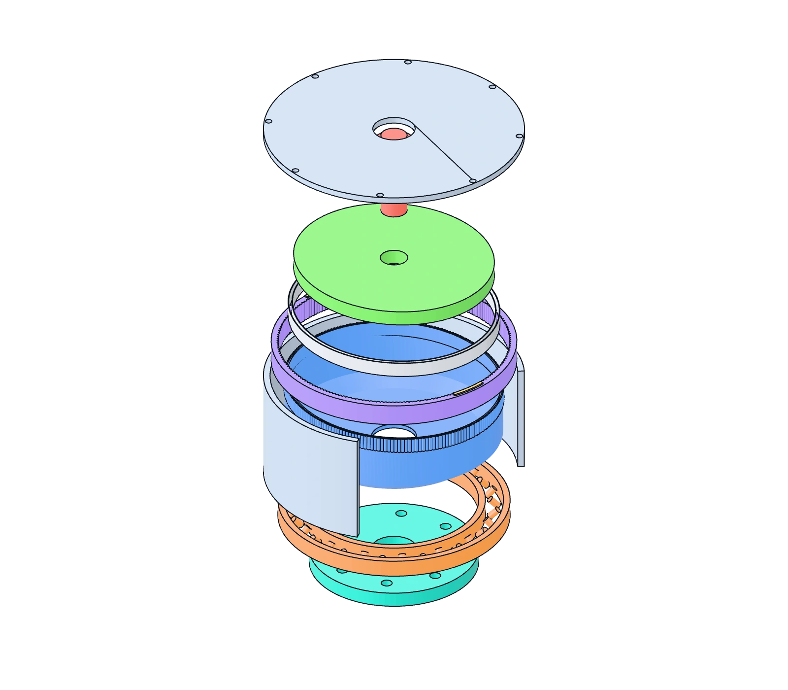
Exploded generic harmonic drive with a cup flexspline, elliptical wave generator, flexible bearing, circular spline, cross-roller bearing and output flange.
Keyboard controls

Arrow keys orbit, plus and minus zoom, Home resets. Use Tab and Enter to select parts; arrow keys adjust sliders.

AssembledExploded

Cup-mouth deflection is magnified ×4; the cup base follows the output. Highlights indicate two major-axis engagement directions. Schematic teeth and radial display clearance do not represent solved contact.

End view: the ellipse and two major-axis engagement zones rotate inside the fixed circular spline; the flexspline output marker rotates slowly in reverse.

End-view phase diagram

Two major-axis engagement zones

Flexspline output marker

Adjust the phase to compare engagement direction and output angle.

Output angle: 0.00°

2D schematic separation

Nine simplified component layers. Spacing follows the separation slider; the selected part is highlighted.

Selected part: Cup flexspline

Assembly: input shaft → wave generator and flexible bearing → cup flexspline → output flange

Preparing the 3D view. Calculations, the phase diagram and part details are available.

Arrow keys orbit, plus and minus zoom, Home resets. Use Tab and Enter to select parts; arrow keys adjust sliders.

Fixed circular spline · flexspline output · generic kinematic schematic

Model and equation limits

With the circular spline fixed, wave-generator input and flexspline output: i = ninput / noutput = −zf / (zc − zf). The default 200 / 202 teeth give i = −100: one input turn produces −3.6° of output.

Nominal pitch radii are rf = m zf / 2 and rc = m zc / 2; w₀ = rc − rf = m (zc − zf) / 2. Fixed m = 0.5 mm and a two-tooth difference give w₀ = 0.5 mm. The display uses 4w₀ = 2 mm.

The cup-mouth profile has two radial waves, tapering toward the base. The elliptical wave generator and flexible bearing are schematic; tooth positions follow output rotation. This is neither a conjugate tooth surface nor an elastic finite-element solution.

The magnified view adds radial offset and clearance to the circular spline for visibility. Highlighted zones indicate engagement directions only; they cannot establish tooth interference, contact pressure or assembly tolerance.

Loads, stress, backlash, efficiency, lubrication and life are not calculated. Part cards list common material families; grades, heat treatment and manufacturing requirements depend on the actual design.

Original generic parametric schematic. No vendor CAD, geometry or material data is reproduced. Interactive geometry and the static GLB share one generator; the reference explains the motion only.